Experience
This section lists some of the projects that I have worked on during my career. Professional and academic.
A System for Testing a Jet Fighter Component
Professional
Solution Description
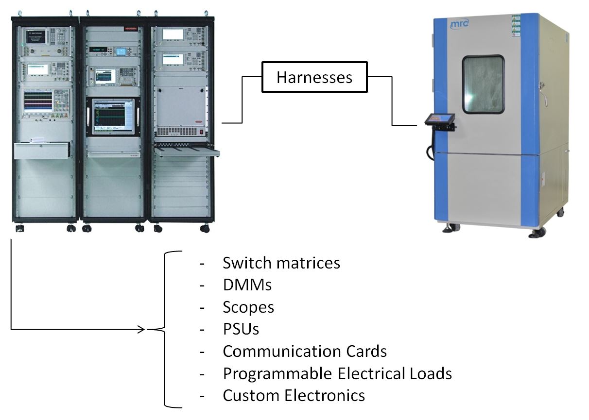
For this project a jet fighter component needed to be tested functionaly and under harsh environmental conditions. Therefore, a test system was developed that could control over 30 instruments and was able to control an environmental chamber (thermal and vibration). The instrumentation included:
- Multiple switching matrices;
- Multiple DMMs;
- Multiple Scopes;
- Various PSUs;
- Various programmable electrical loads;
- Custom PCBs
- Multiple communication cards
To better utilise the environmental chamber - it was decided that three units would be tested at once. Because of that - most instruments had duplicates in the system, to ensure that each UUT can use their respective instruments in parallel, therefore shortening the overall test time. Although, some instruments had to be used as shared resources, due to cost savings.
In the end, the system would carry out over 20 000 tests per UUT.
Prosthetc Hand Control Using EMG Signals and Machine Learning
Academic
Solution Description
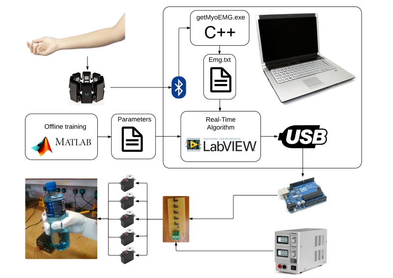
This was a final year MEng project. The purpose of the project was to use a publicly available surface EMG signal database to compare a number of machine learning algorithms. Once the best performing algorithm was found - it was used to build and control a prosthetic hand prototype.
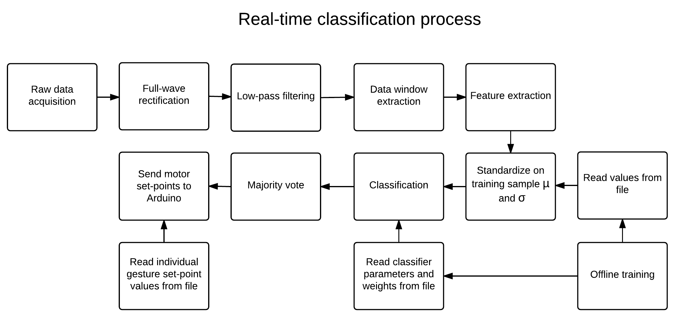
The system used a python script to automate the training data acquisition process. The data would then get used by a Matlab script to train a Multilayer Perceptron model. The obtained coefficients would then be used by a control algorithm written in LabVIEW to control the prosthetic hand in real-time. This was achieved by executing pre-defined gestures, by controlling servo motors via an Arduino Uno, based on data received from the Myo armband.
Selective Colour Tracking Algorithm Using a Webcam and a Pan/Tilt Mechanism
Professional
Solution Description
This was a project meant to demonstrate the capabilities of the myRIO. Utilizing only a myRIO, a webcam and a pan/tilt mechanism - the system was able to accurately track a user selected colour by keeping the camera image centered on the the chosen colour. The colour tracking was done using an in-built machine learning function provided in LabVIEW. The camera feed was divided into 81 areas and each area was tested, if it it’s close enough to the selected colour. All of the processing was done on the myRIO.
In addition, the myRIO transmitted the camera image wirelessly to a user interface and allowed the user to control the camera pan and tilt manually. The video was transmited using UDP due to some frame loses being acceptable for playback and network streams was used for handling commands, to ensure no commands were lost.
The whole project took a couple of weeks to complete.
Micromachining Laser Workstation
Professional
Solution Description
The system is meant to be used for a large variety of tasks on a very small scale, that include:
- Laser micro drilling;
- Laser micro cutting;
- Lassr micro marking;
- Laser welding;
- Multiphoton polimerization;
- Laser ablation;
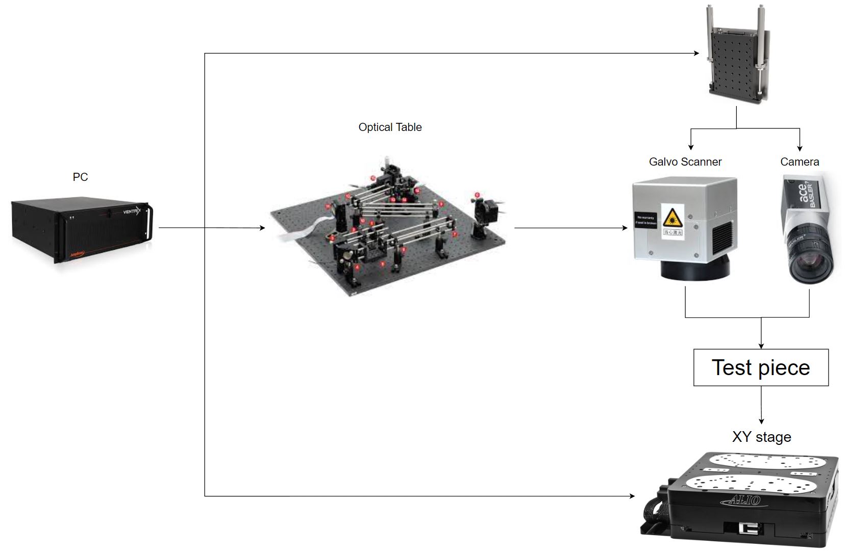
To be able to achieve all of the above, the system uses laser optics, very precise motion stages and galvo scanners. In addition, it also can control linear and rotational axes, polarization rotators, laser power attenuators, beam expanders and stabilizers - giving it precise control of the process being carried out.
All of the above devices and many others are integrated together using a single application. Some of the features supported by the software include:
- The ability to implement the desired process as a sequence of steps;
- Changing of device parameters before and during the process;
- Device calibration;
- Support for fabricating basic shapes, such as, lines, arcs, circles;
- Support for fabricating DXF, STL and image files;
- Manual control of each device;
- PLC support;
The solution acts as a base, that is being used to produce tens of slightly different systems every year.
A System for Testing 8 Missle Triggering Modules at a Time
Professional
Solution Description
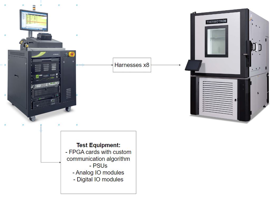
The system was designed to test 8 products at a time. Each product was a missle triggering module, that needed to be tested under real world conditions, using an environmental and vibration chamber.
The product used a custom communication protocol, which was implemented using an FPGA. In addition, power supplies, switching hardware, digital and analog IO were used to test each product. Most of the testing consisted of using black box type algorithms provided by the customers, so that the inner workings of the products were not know. This made developing the system significantly harder, especially when problems would arise.
However, the system was succesfully deployed, it helped reduce the testing time for each unit significantly and eventually a second system was ordered as well.
Datalogging System for Testing Wind Turbines
Professional
Solution Description
The system was designed to be used as a data logging center for testing and characterising wind turbines. Every few months a new wind turbine would arrive, that could be much smaller or bigger than the previous one, would have greatly different measurement requirements, would likely be made by a different manufacturer and therefore would have different interfacing requirements.
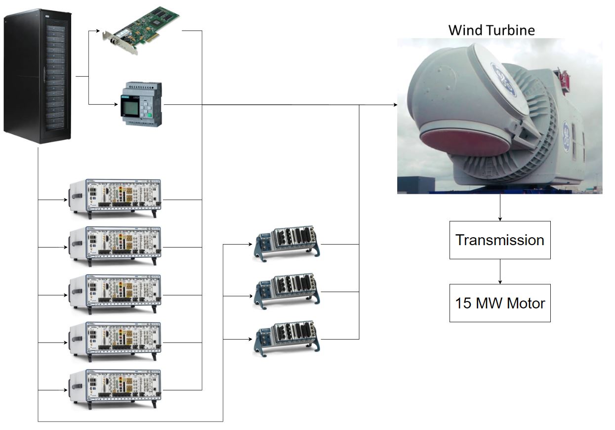
Because the wind turbines under test could be so different, the system was designed to be highly reconfigurable, so that more or different measurement devices could be added with minimal effort. To achieve this National Instruments hardware was used, which on average included:
- 5 PXI chassis
- 3 cDAQ chassis
- A reflective memory module
- Some type of PLC or similar device for interfacing with the turbine
While the PXI chassis were mainly used for outside signals, such as, voltage, current, velocity, force and similar measurements, the cDAQ chassis would measure similar signals, but would be located inside the nacelle of the turbine, due to their ruggedness. The reflective memory module was used to allow the data logging system to communicate with other systems that were involved in controlling and testing the wind turbine. Typically, the system would be logging 1000 to 1700 individual signals, sampled anywhere from 200 Hz up to 100kHz. Due to large amounts of data being logged, that system would regularly fill up a 40TB+ of space. The data was also synchronised to at least microsecond accuracy, while the data acquisition equipment was scattered across the whole building.
Such a solution allowed our customers to complete many trials for many different wind turbines, while keeping the setup time for each new turbine to a minimum.
Systems for Testing Railway Signals, Points and Data Link Modules
Professional
Solution Description
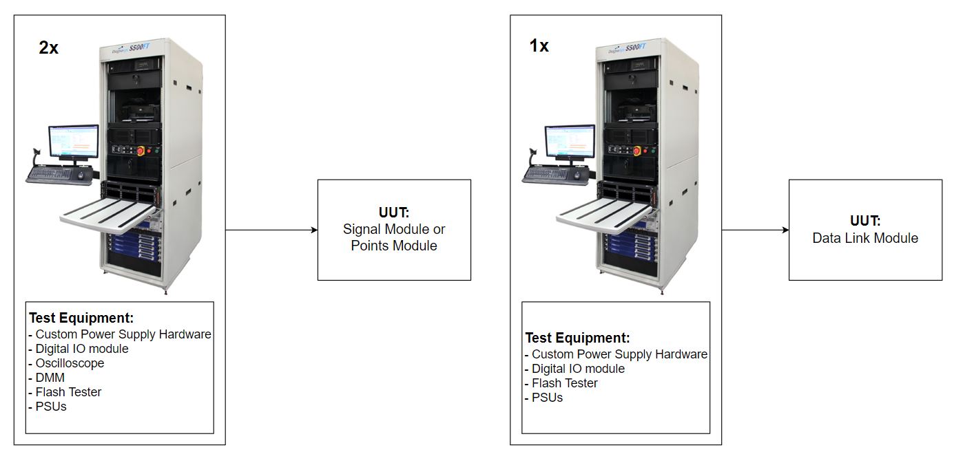
Two different systems were designed for the project. One that could intercheangibly test either Signals or Points modules. And one that could test Data Link modules (sort of a repeater for the previous two). The testing would be done either for new modules or it would be used for servicing and repairing old ones.
The Signals and Points test system would allow the user to install the unit under test (UUT) in a pull-out drawer, connect the appropriate harness, push the drawer in, enter test information and press start. The system would then automatically make electrical connections to the appropriate instrumentation, such as, oscilloscope, power supplies, digital multimeter, flash tester and other IO. Finally, since the test procedure involved using high voltage and current - a light curtain was installed, that would shut down the power to the UUT, if an operator decided to touch the product for whatever reason.
The data link module test system would have similar functionality as the Signals and Points test system, however it had less instrumentation, was simpler and, in turn, much cheaper.
In total, there were 2 Signals and Points test systems produced and 1 Data Link test system. The systems were designed to be in use for over 20 years, with components or replacements relatively easily available. In the end, they allowed our customer to test, service and repair hundreds of thousands of products a year, allowing for a much quicker turn around, than testing each product manually.
Re-design of a Commercial Aircraft Manual Test System into an Automated One
Professional
Solution Description
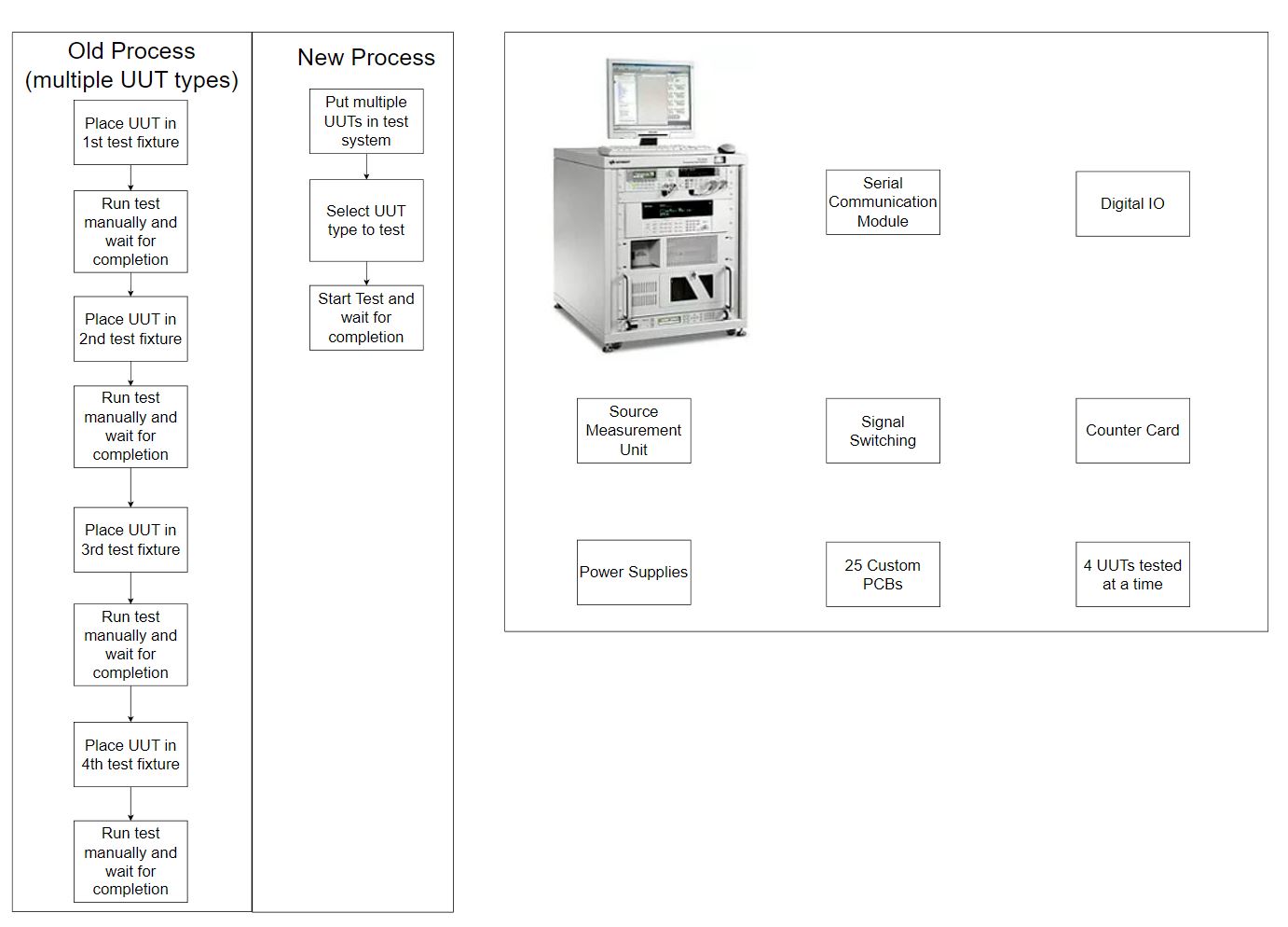
The goal of the project was to take an existing automated test solution that mainly relied on batch scripts and a lot of manual labor from the test engineers and turn it into an automated one. For that purpose, a system was designed that could test 4 products at the same time by simply entering each product details and pressing a single button. The interface was purposefully desgined to be as simple as possible to reduce
operator mistakes and to be very easy to learn how to use.
A grand total of 25 custom PCBs were designed to interface the Units Under Test (UUT) with a selection of instruments, provide signal conditioning and signal switching. The instruments included:
- Serial communication module (utilizing UART);
- Signal switching hardware;
- Digital IO module;
- Source Measurement Unit (SMU);
- Counter card;
- Numerous power supplies;
- JTAG module;
Developing the test software was a challenge, due to part of the source code missing for the original test system and the test specification not always matching how the products were behaving. However, due to proactively communicating with the customers, the missing pieces were eventually reverse engineering and the new test system was completed.
Not only did the final solution reduce the amount of manual labour required to test the UUTs, but it also reduce the time needed to test the units by about 70% percent.
Software to Monitor the Live Performance Metrics of a Coal Burning Plant
Professional
Solution Description
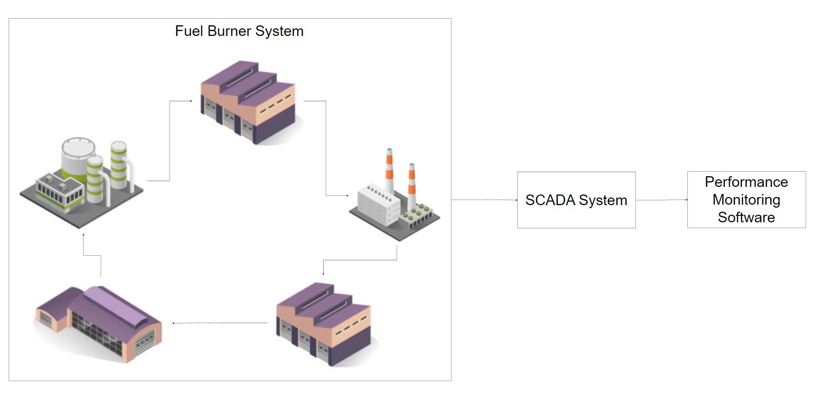
The goal of the project was to take an old piece of software written by the customer for monitoring the performance of a fuel burner, update it and add new features. This was needed, as the old software became very difficult to maintain, due to the old LabVIEW code not following good development practices.
For the new software, the previous functionality was left in tact as much as possible, but written in a more maintainable way. Parts of it that were not clear, were extensively discussed with the customer to provide the most suitable solution. New features were added, that greatly improved the user experience and allowed the customer to do their work more efficiently.
Since the software was written to have a simulation mode (using previous experiment data), the comissioning of it was supposed to be carried out using simulation mode. However, upon arriving on-site, the customers wanted to fire up the actual fuel burning plant. After a few of hours testing the functionality and fixing a few calculation mistakes - the customers were hapily running experiements and testing the new software themselves.
Overall, the project allowed the customers to carry out their work more quickly and to interpret their test data in a much more convienient way.
Automated Pressure Sensor Testing System
Professional
Solution Description
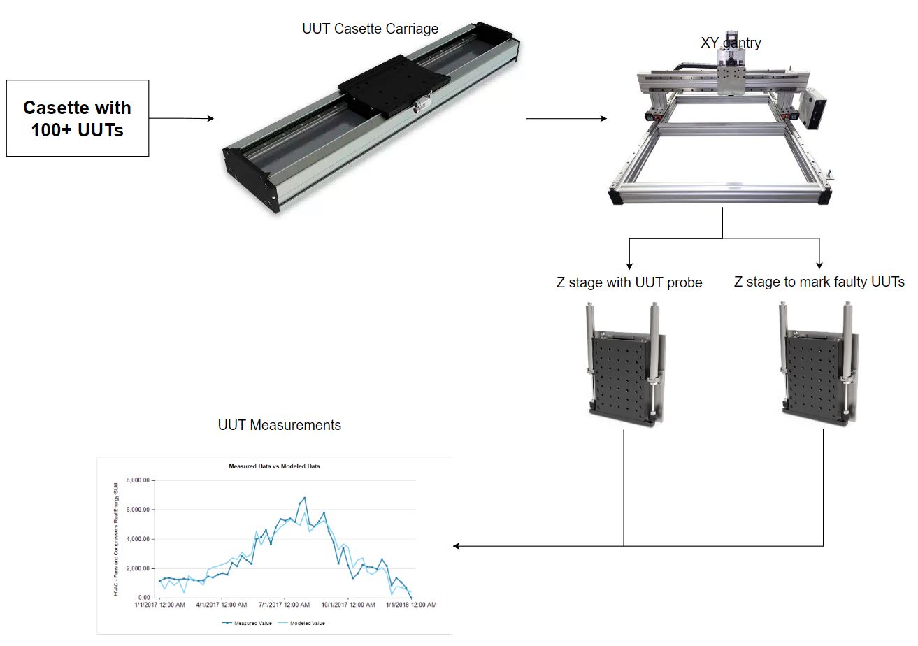
This project designed to be used in a manufacturing fascility, to measure the force vs resistance response of for single point touch, finger electrodes. The electrodes that did not meet the required tolerances would be marked to be discarded.
The products were tested by pressing on them with a probe attached to a Z linear stage, that had an integrated load cell. While pressing on the product, the probe would also make contact with the UUT using spring loaded probes to measure the resistance. By doing so a force vs resistance curve could be measured for the full range of the product. The requirement was that each sensor must be measured in under 7s. The results were evaluated after all of the sensors were tested and a marker attached to a second Z linear stage would mark the faulty products.
A test run would begin by the operator loading in a casette, which contained more than a 100 sensors, entering test data and pressing start. The casette would then be pulled into the main test chamber, where an XY gantry would position the two Z stages. The whole system was enclosed and had an E-STOP circuit that would trip, whenever an operator would try to open one of the doors or panels, ensuring compliance with the safety standards in the UK.
The system was powered by a single cRIO that ran both the control code (real-time and FPGA) and the embedded UI. It was required to control a total of 5 motors, perform force and resistance readings, along with some digital IO for the safety circuitry, limit switches and other functions of the system.
Double Hexapod System for Testing Train Carriage Gangways
Professional
Solution Description
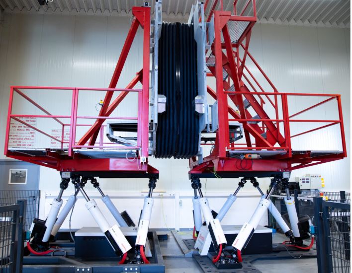
The purpose of the project was to use two hexapod platforms to simulate the motion between two train carriages, so that a flexible gangway can be installed between them and tested for it’s durability over it’s estimated lifecycle.
The customers had acquired a lot of data for the train tracks their products were going to be used on and already had an older solution. However their solution was limited to only 3 Degrees of Freedom (DOF), while they needed the full 6 DOF to be able to simulate all the use cases.
A solution was designed, while colaborating with two other companies, that would provide the necessary 6 DOF and would automate the whole test process. It involved:
- 2x Hexapod platforms;
- A real-time controller to synchronise the platforms;
- Some digital IO for the safety features of the system;
- An industrial PC to provide a user interface and to log the data;
The test process involved data taken from the worst case train track portions and repeating that worst case scenario as many times as it would be repeated during 20 years of real operation. During the test, precise position and force measurements were logged to evaluate the performance of the gangway. The gagnway itself would be inspected for wear and tear at predefined points in the test process.
Overall, this system allowed the customer to not only increase the range of test scenarios, but also to acquire much more useful test data and to reduce the overall test time, as the newer hardware allowed for faster operation.
A System to Calibrate a Wind Turbine Sensor using 12 Hydraulic Rams
Professional
Solution Description
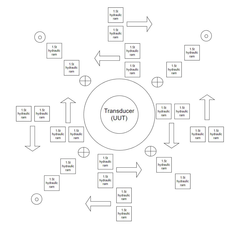
The purpose of the project was to develop a system, that would allow calibrating a large wind turbine transducer, so that it’s measurement accuracy could be ensure, when it is being used to test wind turbines. The calibration was supposed to be carried out by running user defined calibration profiles and measuring the displacement and force readings of the transducer. A custom solution was necessary, as, at the time, there was only one fascility in Europe that could calibrate such transducers, however the could not accommodate such a large size.
To achieve the above functionality, the transducer would be installed in a large fixture with 12 pairs of hydraulic rams. Each ram capable of producing 1.5 tonnes of pressure. The rams would be installed in such a way, that that they could apply forces on the transducer in 6 Degrees of Freedom (DOF). Each hydraulic ram pair would be coupled with an LVDT and load cell sensors, for measuring displacement and pressure. Each pair would be controlled by a PID loop to maintain the desired pressure.